
THE SIDE VALVE ENGINE
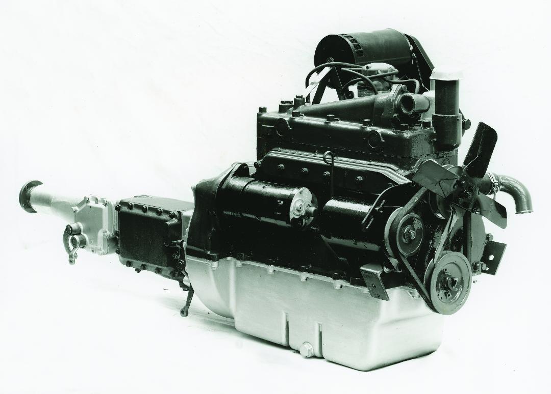
A very early home market engine, with gearbox fitted. While this engine had no oil filter, cast alloy oil filler cap, four blade fan and the cooling system was non pressurised, it received no major changes throughout its production life
Background
Unlike the OHC engines fitted to the larger Morris Six and Wolseley 6/80 (which had an interesting lineage) the power plant for the MO was something of an afterthought. Alec Issigonis favoured a flat four engine for both the Mosquito (later renamed the Minor) and the Oxford. Issigonis had previous experience with that type of engine in the ‘Gutty’, a four wheel drive military style jeep produced by the Nuffield group. The benefits of the flat four was that it was shorter, thereby allowing it to be moved forward which resulted in more cabin space and more weight transferred to the front of the car. The latter to test his nose heavy theory. However, trials were carried out with both cars and after numerous teething problems, combined later with boardroom intervention, the idea of a flat four engine was abandoned in favour of something more conventional. The crunch came for the Oxford after a meeting on 24th June 1947 when the flat four project was laid to rest.
With the first production line car scheduled for completion in June 1948 this put great pressure on the Engine Branch to produce a new 1.5 litre side valve engine within twelve months. Unlike the Minor, which ended up using an improved version of the Morris 8 engine coupled to a four speed gearbox, the Oxfords power plant was designed from the ground up. Tom Brown and the staff at Morris Engines completed the task with just one day to spare.
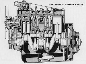
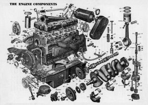
Once in production the engine would remain with the car during its full production period, between 1948 and 1954, as well as being used in commercial variants and the J van. The design team must have ‘got in right’ as there were only a couple of refinements made during this period; such as the fitting of oil filters in 1949. At the same time the oil pressure relief valve, which had previously been an independent fitting, was incorporated into the oil filter mounting. There was also a slight modification of the centre boss of the timing gear.
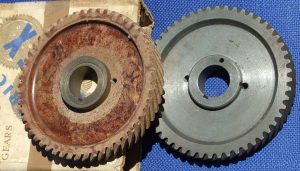
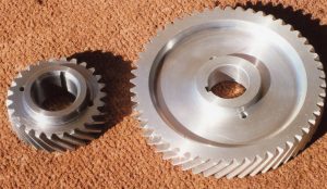
In later life the engine’s achilles heel was the timing gear. The originals were fibre and with age and wear they would occasionally fail. Many after market replacements have been made using a more modern fibre based compound, an alloy compound, bronze, steel and even a type of nylon. Some of the metal gears work well but as a trade off are not as silent as the originals.
Another thing that could occur, again later in life, is cracking of the block between the rear valve seats, but in a lot of cases this is due to poor maintenence combined with overheating the engine.
While it could never be described as a performance engine for its time it was quite adequate and comparable to similar cars on the market. In fact a well maintained engine could be quite spritely, as well a being robust and reliable. These trusty side valve engines are still capable of being run all day long without missing a beat.
Engine Description
This four cylinder side valve engine is built in unit construction with a single plate dry clutch and four speed gearbox.
It has a robust four throw crankshaft, carried in three renewable white metal steel backed bearings fitted without shims. The thrust is taken by the rear bearing which is flanged for this purpose.
The connecting rod big end bearings are also renewable white metal lined steel backed bearings fitted without shims. The little end embracing the gudgeon pin, is slotted and fitted with a clamp screw and spring washer, which serve to lock it solidly to the gudgeon pin.
The pistons are of tin coated aluminium alloy and are fitted with two compression rings and one oil control ring.
The camshaft is supported by three bearings in the cylinder block casting and is driven from the crankshaft by helical gears. The camshaft bearings are pressure fed with oil from the main oil gallery. The camshaft operates the valves through the medium of chill cast tappets, located in guides cast integrally with the block. Provision for adjustments of the tappets is made by the orthodox tappet head screw and lock nut.
Lubrication System
The oil supply is carried in the sump below the cylinder block. An oil indicator dipstick is fitted on the right hand side of the engine and the oil filler is situated at the front of the cylinder head.
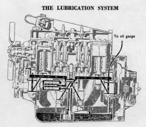
The gear type oil pump is carried in the sump of the engine and is driven from a helical gear on the camshaft. It draws the oil from the sump through a floating filter and thus delivers clean oil to the pump shaft tunnel.
At its upper end the pump shaft tunnel connects with a horizontal oil gallery running from front to rear of the engine, from which the oil is fed to the camshaft bearings and crankshaft main bearings through drilled passages.
Drilled passages in the crankshaft provide lubrication for the big end bearings, the surplus oil from which splashes on to the camshaft, tappet gear and cylinder walls.
An oil pipe connects the rear end of the main oil gallery with the oil gauge on the instrument panel. A pressure release valve of the non adjustable ball type is mounted on the outside of the engine, integral with the external bypass filter unit, to deal with cases of excessive pressure.
A bypass valve is provided to ensure that in the event of pressure building up inside the filter, or the filter becoming blocked, oil is fed to the main gallery direct. The filter should be renewed every 12,000 miles (20,000 km).
The timing gears are well lubricated by oil direct on them by a hollow bolt screwed into the cylinder block and fed by a drilled passage from the main oil gallery.
Cooling System
The cooling system is of the thermo syphon impeller assisted type, with thermostat control. The water is circulated from the base of the radiator by the pump and after passing around the cylinders and cylinder head it reaches the header tank via the thermostat and top water hose.
Air is drawn through the radiator by a fan which is mounted on the water pump spindle and both are driven by a belt drive from the crankshaft. On early cars the fan was made up of four blades and the cooling system was non pressurised. Later cars had a pressurised system and a six blade fan.
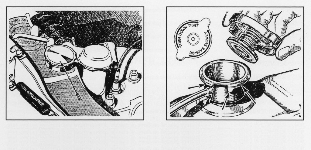
The radiators in non pressurised cars had a brass screw on cap, while the pressurised system had a standard pressurised cap.
Ignition System
The ignition equipment is of the coil type and is provided with an automatic advance mechanism which relieves the driver of the necessity of adjusting the timing. Its advantages are particularly evident when accelerating and during hill climbing, since the danger of knocking or pinking through excessive advance is very much reduced.
The automatic advance device is housed in the distributor unit and it consists of a centrifugally operated mechanism by means of which the ignition is advanced in proportion to the engine speed.
The distributor type on early models is a Lucas Model DKYH4A (Service No. 40152). These marks, together with a manufacture date, are stamped on the side of the distributor. Commencing at Engine No. 56344, a distributor of the same model but Lucas Service No. 40237 was fitted, but this was superseded at Engine No. 150541 by the model D2A.4 (Lucas Service No. 40358), with a high lift cam and inbuilt suppressor.
The original coil was a Lucas Model Q12 (Service No. 45020). These marks are stamped on the base of the ignition coil.
The original spark plugs fitted to the car were manufactured by the Champion Sparking Plug Company. Champion L10, 14mm with 1/2 inch reach. The gap between the points of between .018 in to .022 in (.46mm to .56mm).
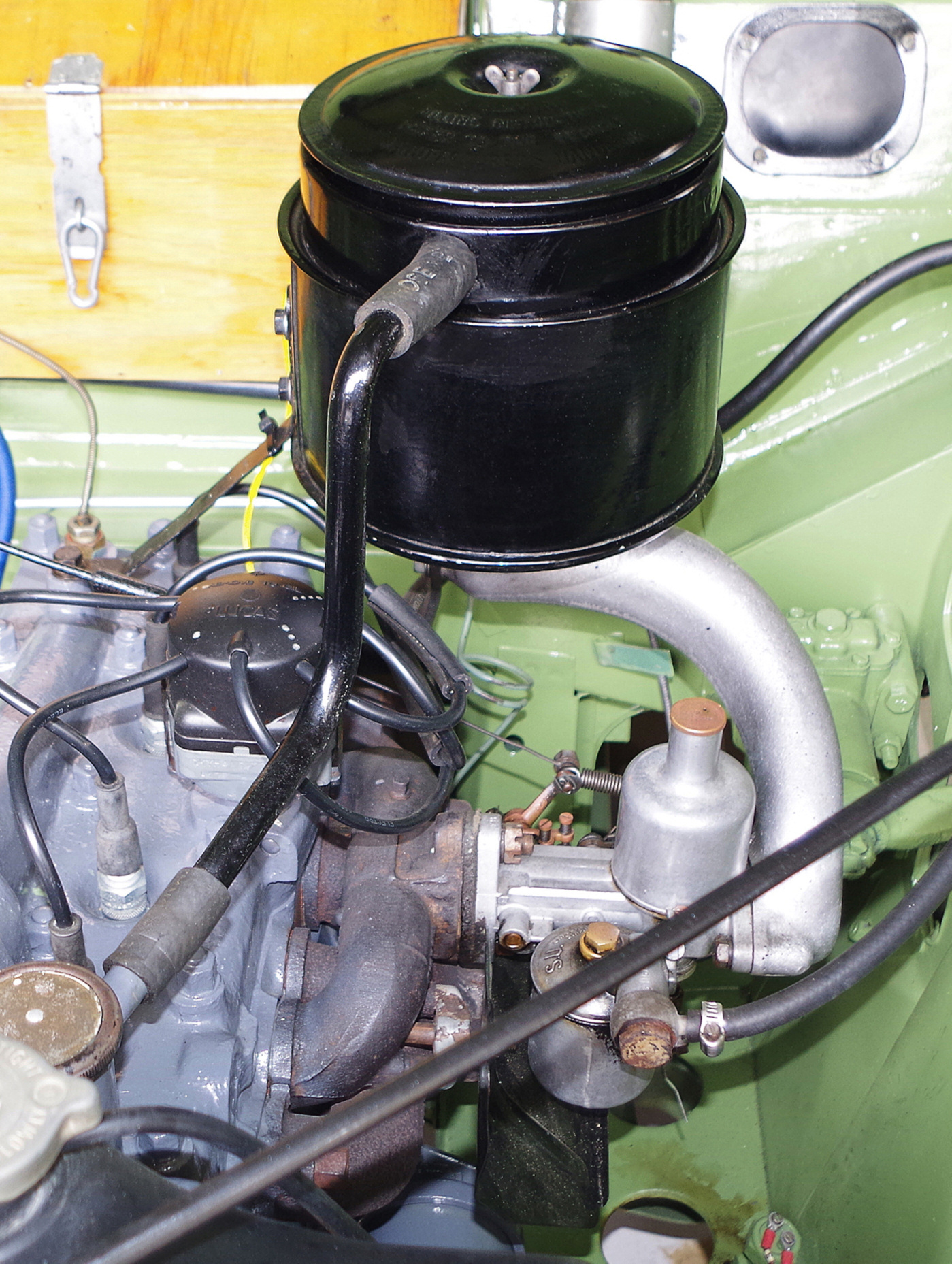
Right: An Export model car showing the oil bath air cleaner.
Carburetter and Fuel System
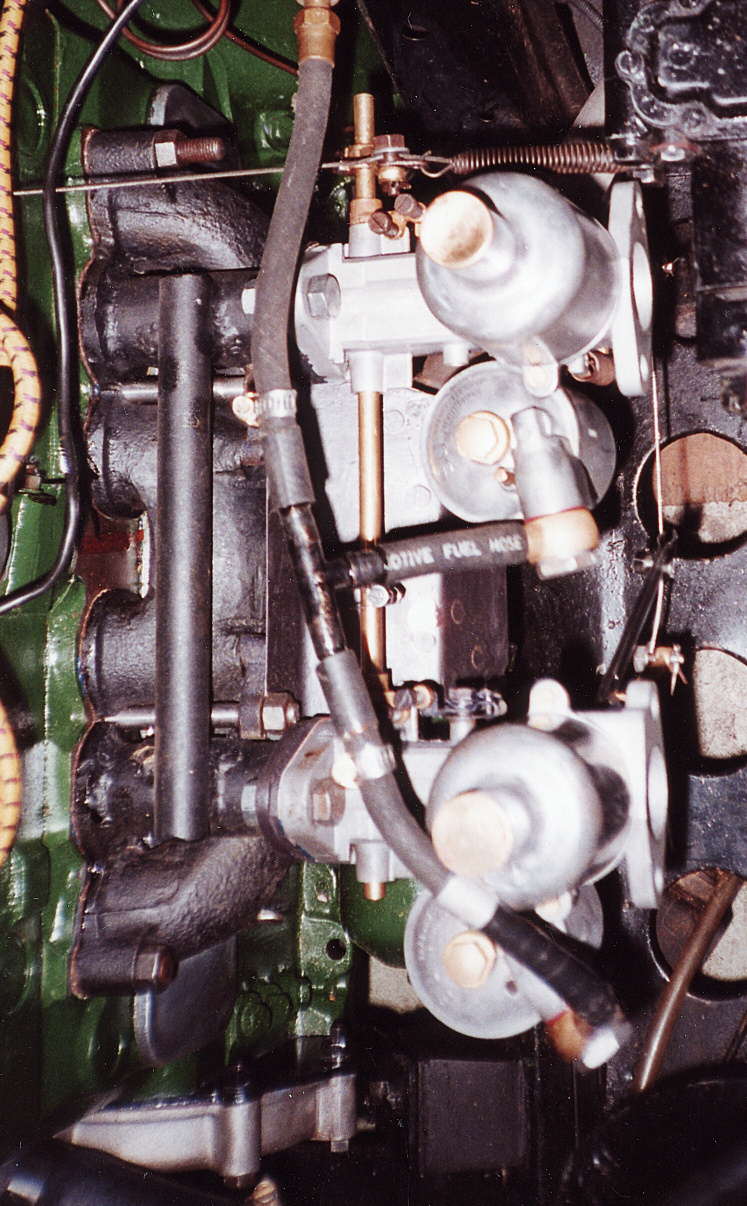
The carburetter was manufactured by SU and is of the controllable mixture jet type, fitted with an air cleaner. The air cleaner differed between Home and Export models. The Home version is the more familiar horizontal type whereas the Export air cleaner is upright and of the oil bath type.
A damper is provided consisting of a plunger and non return valve attached to the oil cap nut, which operates in the hollow piston rod which is partly filled with oil. Its function is to give a slightly enriched mixture on acceleration by controlling the rise of the piston and prevent piston flutter.
The petrol pump is an SU Type L, 12 volt (positive earth) electric pump. On early models it was fitted on the left hand side of the bulkhead, but on later models fitted on the right hand side.
Left: A twin carburettor setup fitted to the MO engine, which is claimed to increase performance by up to 25%. This particular unit was custom made but by an engineer using all original parts.